Leak Test Cell with Robotic Handling
Client: Leading Plastic Moulding Company
Part: Automotive Tyre Pressure Sensor (Overmoulded Assembly)
Machine supplied: Fully Automatic Leak Test Cell with Robotic Handling
Robot: Fanuc 6-Axis with Multi-Part Gripper
Capacity: 6-Up Part Handling (6 Assemblies Per Cycle)
Test Method: Air Decay Leak Testing with MALT Units
Operations: Insert Bowl Feed → Robot Load to Moulds → Overmoulding → Robot Unload → Cooling → Leak Test → Pass/Fail/QC Segregation
The Challenge
A leading plastic moulding company producing automotive tyre pressure sensors needed a fully automatic leak test cell integrating overmoulding, testing, and packing. The requirements included:
- Automated insert feeding from bulk supply
- Robotic loading of 6 metal inserts into overmoulding tool
- Integration with customer-supplied overmoulding machine
- Automatic unload and controlled cooling before testing
- 100% leak testing of overmoulded assemblies
- Temperature stabilisation ensuring accurate test results
- Three-way segregation (pass, fail, QC sample)
- Vision inspection verifying insert presence and assembly quality
- High-volume production with minimal operator intervention
Tyre pressure sensors monitor wheel pressure in real-time, transmitting data to vehicle safety systems. Leaks compromise sensor accuracy and cause:
- False low-pressure warnings (driver nuisance)
- Missed actual low-pressure conditions (safety risk)
- Premature sensor failure from moisture ingress
- Warranty claims and customer dissatisfaction
Manual testing couldn’t achieve 100% verification at production volumes, and inconsistent cooling caused false failures from thermal expansion/contraction during testing.
The Solution – Leak Test Cell
TQC designed a robotic leak test cell integrating vibratory bowl feeding, Fanuc 6-axis robot handling, overmoulding machine integration, indexing cooling system, 6-channel MALT air decay leak testing, vision inspection, and automatic pass/fail/QC segregation. The robot handles 6 parts per cycle using a multi-part gripper, loading metal inserts into the mould tool and unloading finished assemblies to the cooling system. After temperature stabilisation, assemblies undergo simultaneous air decay leak testing using 6 MALT modules. Vision inspection at multiple stages included verifying insert presence in the mould tool and finished assembly quality. Automatic segregation routes passed parts to packing boxes, failed parts to reject bins, and QC samples to inspection chutes.
Technical Overview
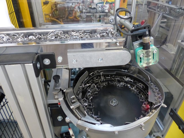
Vibratory Bowl Feeding of Metal Inserts
Bulk Part Feeding: Vibratory bowl feeder orients and presents metal inserts for robot pickup:
Bowl Feeder Operation:
- Metal inserts loaded into circular bowl in bulk
- Electromagnetic vibration drives parts up helical track
- Tooling features along track orient inserts to correct position
- Exit track presents 6 inserts in row at known pitches for simultaneous robot pickup
Why Vibratory Feeding: Metal inserts arrive from supplier in bulk containers. Vibratory feeding eliminates manual presentation, providing continuous part supply without operator involvement.
Orientation Tooling: Track features reject incorrectly-oriented inserts:
- Width restrictions pass only correctly-oriented parts
- Height steps tip misoriented parts back to bowl
- Air jets blow incorrectly-aligned parts back
- Vision sensor at exit verifies correct orientation before robot pickup
Feed Rate Management: Bowl vibration amplitude adjusts based on robot cycle demand, maintaining constant supply without overfilling exit track.
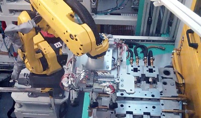
Fanuc 6-Axis Robot with Multi-Part Gripper
Robotic Material Handling: Fanuc 6-axis robot manages all part transfer operations:
Robot Specifications:
- Industrial 6-axis articulated arm
- Payload capacity sufficient for 6-part gripper + assemblies
- Repeatability: ±0.05mm (critical for mould loading precision)
- Work envelope covers bowl feeder, mould tool, cooling system, and leak test stations
Multi-Part Gripper Design: Custom end-of-arm tooling handles 6 parts simultaneously:
Gripper Configuration:
- 6 individual pneumatic grippers mounted on single frame
- Spacing matches mould tool cavity positions (typ. 100-200mm centres)
- Each gripper independently actuated for selective pickup/release
- Vacuum cups or mechanical fingers (depending on insert geometry)
Why 6-Up Handling: The overmoulding machine uses a 6-cavity tool. Single-part handling would require 6 robot cycles per mould shot, creating bottleneck. 6-up gripper matches mould capacity:
- One robot cycle loads all 6 inserts
- One robot cycle unloads all 6 finished assemblies
- Robot cycle time matches mould cycle time
Robot Cycle Sequence
Full Automation Workflow:
1. Insert Pickup from Bowl Feeder:
- Robot positions gripper above bowl feeder exit track
- Vision inspection confirms 6 inserts present and correctly oriented
- Gripper descends, vacuum/mechanical grippers engage all 6 inserts
- Robot lifts and verifies positive grip on all parts (pressure sensors confirm)
2. Load Inserts to Overmoulding Tool:
- Mould tool on 2-position indexing table rotates to load position
- Robot positions gripper above open mould cavities
- Gripper descends, inserting metal parts into cavity locators
- Release command, robot withdraws
- Vision inspection (mould-mounted cameras) verifies inserts correctly positioned
3. Mould Tool Indexes and Overmoulding Occurs:
- Indexing table rotates 180° (loaded tool to moulding position, previously-moulded tool to unload position)
- Injection moulding machine clamps, injects plastic around inserts, cures, opens
- Cycle time: Typical 30-60 seconds depending on part geometry and plastic material
4. Unload Overmoulded Assemblies:
- Robot positions gripper above open mould at unload position
- Gripper engages 6 finished assemblies (still warm from moulding)
- Robot extracts assemblies, verifies positive grip
- Assemblies transfer to cooling system
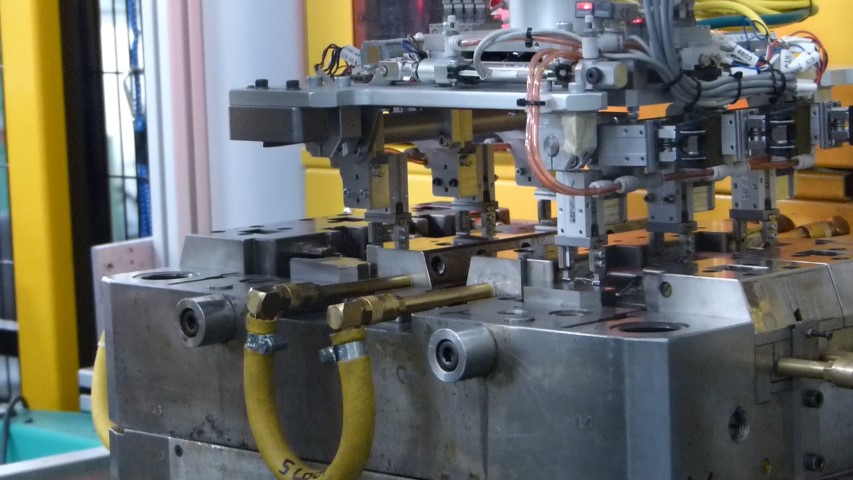
Integration with 2-Position Indexing Rotary Table
Overmoulding Machine Configuration: Customer-supplied injection moulding machine with 2-position rotary table:
Rotary Table Operation:
- 6-cavity mould tool mounted to rotary platen
- Position 1 (Load/Unload): Robot access for insert load and assembly unload
- Position 2 (Mould): Clamping and plastic injection
- 180° indexing alternates positions
Why 2-Position Indexing: Allows simultaneous operations:
- While robot loads inserts at Position 1, machine moulds at Position 2
- While robot unloads assemblies at Position 1, machine moulds next cycle at Position 2
- Eliminates waiting for mould open/close, maximising throughput
Integration Challenges Addressed:
- Robot interlocked with mould machine safety (cannot move during clamp)
- Mould cannot close until robot clears (light curtains verify)
- Table indexing synchronised with robot cycle completion
- Vision inspection confirms inserts loaded before mould closure permission
Indexing Cooling System
Temperature Stabilisation Before Testing: Assemblies fresh from the mould are too warm for accurate leak testing:
Why Cooling Matters:
- Plastic thermal expansion creates dimensional changes
- Warm air inside sensor expands during test, masking small leaks
- Temperature gradients cause pressure drift during test
- Inconsistent temperatures create false failures
Cooling System Design:
- Indexing conveyor with multiple positions (typ. 10-20 stations)
- Each position holds 6 assemblies (one robot cycle batch)
- Assemblies advance one position per robot cycle
- Total residence time: 5-10 minutes (sufficient for stabilisation to ambient ±2°C)
Indexing Operation:
- Robot places 6 warm assemblies at entry position
- Conveyor indexes, advancing all assemblies one position
- Oldest batch (fully cooled) reaches exit position
- Robot picks cooled assemblies for leak testing
- Empty position created for next warm batch
Ambient Cooling vs. Forced Cooling: System likely uses ambient air cooling:
- Forced air (fans) would create uneven cooling
- Ambient cooling provides uniform temperature stabilisation
- Longer cooling time acceptable in high-volume production
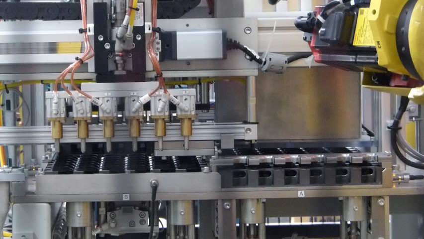
6-Channel MALT Air Decay Leak Testing
Simultaneous Testing of 6 Assemblies: Six independent MALT (Multi-Application Leak Tester) modules perform parallel leak testing:
MALT Configuration:
- 6× MALT LT201 valve modules and controllers
- Each module tests one assembly independently
- Common test parameters (pressure, time, limits) programmed across all channels
- Individual pass/fail results for each assembly
Air Decay Test Procedure:
1. Assembly Positioning: Robot places 6 cooled assemblies into test fixtures
2. Sealing: Test fixtures seal against sensor housings:
- O-ring seals on sensor exterior
- Pneumatic clamps secure assemblies
- Seal verification (pressure test confirms no external leaks)
3. Pressurisation: Test pressure applied internally (typical 1-3 bar):
- Fill phase: Rapid pressurisation to test pressure
- Stabilisation phase: 2-5 seconds for pressure equilibrium
- Test phase: 5-10 seconds monitoring pressure decay
4. Pressure Decay Measurement:
- High-precision pressure transducers measure pressure at test start and end
- Decay calculation: Pressure drop over test period
- Comparison to specification limits
5. Pass/Fail Determination:
- Decay below threshold: Pass (acceptable leak rate)
- Decay above threshold: Fail (excessive leak)
Why 6 Channels: Matches robot 6-up handling. Testing all 6 simultaneously maintains throughput rather than sequential testing that would create bottleneck.
MALT Module Advantages:
- Compact size (mounted close to test fixtures)
- Fast test cycles (total 10-15 seconds)
- High sensitivity (detects leaks <1 cm³/min)
- Proven reliability in automotive production
Vision Inspection at Multiple Stages
Multi-Stage Quality Verification: Vision systems inspect at three critical points:
Stage 1: Insert Presence at Bowl Feeder Exit
- Verify 6 inserts present on exit track
- Confirm correct orientation before robot pickup
- Prevent robot attempting to grip missing/misoriented parts
Stage 2: Insert Position in Mould Tool
- Mould-mounted cameras inspect after robot loading
- Verify inserts fully seated in cavity locators
- Check orientation and alignment
- Prevent mould closure on mispositioned inserts (damage risk)
Stage 3: Finished Assembly Inspection
- Inspect overmoulded assemblies after cooling
- Verify plastic overmould complete (no short shots)
- Check for flash, voids, or cosmetic defects
- Confirm insert not displaced during moulding
Vision Technology:
- Industrial cameras with LED ring lighting
- Pattern matching algorithms comparing to reference images
- Measurement tools verifying critical dimensions
- PLC integration for automatic pass/fail decision
Reject Routing: Assemblies failing vision inspection bypass leak testing and route directly to fail chute.
Pass/Fail/QC Segregation System
Three-Way Sorting After Leak Test: Tested assemblies route to one of three destinations:
1. Pass Chute → Packing Boxes:
- Assemblies passing both vision and leak test
- Robot places into pass chute
- Gravity feed to packing boxes
- Operator removes filled boxes, replaces with empty
2. Fail Chute → Reject Bins:
- Assemblies failing vision inspection or leak test
- Robot diverts to fail chute
- Collect in reject bins for analysis or scrap
3. QC Sample Chute → Quality Inspection:
- Periodic sampling for statistical process control
- Programmable sample rate (e.g., 1 per 100, random selection)
- Detailed inspection by quality engineers
- Dimensional verification, cross-section analysis, leak rate trending
Why Three-Way Sorting:
- Passed parts ready for shipment (no further handling)
- Failed parts segregated for root cause analysis
- QC samples enable process monitoring without disrupting production flow
Chute Design: Gravity-feed chutes guide assemblies to collection points:
- Angled surfaces (30-45°) for reliable sliding
- Impact-absorbing landings prevent damage
- Clear material (polycarbonate) for visual confirmation
- Sensors detect full boxes/bins, halt robot until emptied
PLC Control and Data Logging – Leak Test Cell
Integrated Cell Control: Programmable Logic Controller coordinates all cell operations:
Controlled Equipment:
- Vibratory bowl feeder rate
- Robot motion sequences and gripper actuation
- Mould machine indexing (via handshake)
- Cooling conveyor indexing
- 6× MALT leak test modules
- Vision system triggers and result processing
- Segregation chute routing
Operator Interface:
- HMI touchscreen displaying cell status
- Production counts (total, passed, failed, QC samples)
- Reject rate trending by failure mode (vision vs. leak test)
- Alarm messages and fault diagnostics
- Manual mode for setup and recovery
Data Logging:
- Individual assembly results (serial number if marked, or batch number)
- Vision inspection results by stage
- Leak test results (pressure decay values, pass/fail)
- Cycle times
- Failure modes
- Date/time stamps
Traceability: Data enables:
- Batch tracking for warranty claims
- Process capability analysis
- Identification of process drifts (leak rate trending)
- Correlation of failures to specific mould cavities or process parameters
System Specifications – Leak Test Cell
- Configuration: Fully automatic robotic workcell
- Robot: Fanuc 6-axis articulated arm
- Gripper: Custom multi-part design (6-up handling)
- Insert Feeding: Vibratory bowl feeder with orientation tooling
- Overmoulding Machine: Customer-supplied with 2-position indexing table (6 cavities)
- Cooling System: Indexing conveyor (10-20 positions, 5-10 minute residence)
- Leak Testing: 6× MALT LT201 modules (air decay method, 1-3 bar test pressure)
- Vision Inspection: Multiple cameras at bowl exit, mould tool, post-moulding
- Segregation: Pass/Fail/QC three-way sorting with gravity chutes
- Control: PLC with operator HMI
- Capacity: 6 assemblies per cycle, 100% testing
- Application: Automotive tyre pressure sensors (overmoulded metal insert assemblies)
Key Features – Leak Test Cell
Fully Automatic Operation: Eliminates manual part handling from insert feeding through final packing.
6-Up Robot Handling: Multi-part gripper matches mould capacity, maintaining throughput without robot bottleneck.
Vibratory Bowl Feeding: Continuous insert supply from bulk without operator intervention.
2-Position Indexing Table Integration: Simultaneous robot access and moulding operations maximise productivity.
Indexing Cooling System: Temperature stabilisation eliminates false leak test failures from thermal expansion.
6-Channel Parallel MALT Testing: Simultaneous testing of 6 assemblies maintains production flow.
Multi-Stage Vision Inspection: Verification at bowl exit, mould load, and post-moulding catches defects early.
Pass/Fail/QC Three-Way Segregation: Automatic sorting enables immediate packing of passed parts while capturing rejects and QC samples.
100% Leak Testing: Every assembly verified before shipment, ensuring sensor reliability.
PLC Control with Data Logging: Comprehensive process documentation and traceability.
Results – Leak Test Cell
The fully automatic leak test cell with robotic handling provides 100% verification of automotive tyre pressure sensors at high production volumes. The Fanuc 6-axis robot with multi-part gripper handles 6 assemblies per cycle, matching overmoulding machine capacity and eliminating material handling bottlenecks.
Vibratory bowl feeding provides continuous insert supply without operator loading. Integration with the 2-position indexing table enables simultaneous robot access and moulding operations, maximising throughput.
The indexing cooling system stabilises assembly temperature before testing, eliminating false failures from thermal expansion that plagued manual testing. 6-channel parallel MALT testing maintains production flow while providing high-sensitivity leak detection.
Multi-stage vision inspection catches defects at bowl feeder exit, mould loading, and post-moulding. Early detection prevents defective parts from consuming expensive moulding cycles and test time.
Three-way pass/fail/QC segregation enables immediate packing of verified assemblies while capturing rejects for root cause analysis and QC samples for process monitoring. PLC data logging provides comprehensive traceability for warranty management and continuous improvement.
The automated cell reduced labour requirements, eliminated manual testing inconsistency, and achieved 100% leak verification ensuring tyre pressure sensor reliability in vehicle safety systems.
To view a printer friendly format please click below
Leak Test Cell with Robotic Handling
Related Capabilities
This project demonstrates TQC‘s expertise in:
- Robotic workcell integration
- Fanuc 6-axis robot programming
- Multi-part gripper design
- Vibratory bowl feeding systems
- Injection moulding machine integration
- Cooling system design for thermal stabilisation
- MALT air decay leak testing
- Multi-channel parallel testing
- Vision inspection systems
- Pass/fail segregation automation
- PLC control and data logging
- Automotive production systems
- 100% quality verification
If you need robotic workcell integration with automated leak testing, contact TQC to discuss your requirements.