Automotive Brake Leak and Flow Testing
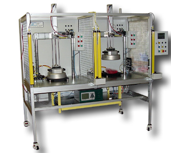
Machine supplied: Brake Leak Testing and Flow Testing Bench with Twin Stations
Client: Leading Automotive Brake Parts Supplier
Part: Disc Brake Assemblies
Throughput: 1 part per minute (60 parts per hour)
Test Methods: Flow Test + 3-Stage Pressure Decay (0.5, 2, and up to 160 bar)
The Challenge
A leading automotive brake parts supplier needed production acceptance testing for high-performance disc brake assemblies. The test requirements included:
- Flow testing to verify hydraulic passages are clear (no blockage)
- Three separate leak tests at different pressures to simulate service conditions
- High-pressure leak testing up to 160 bar (2,320 psi)
- Part marking of passed assemblies for traceability
- Throughput of approximately 60 parts per hour
- Interchangeable tooling for multiple brake variants
Brake assemblies must maintain hydraulic integrity across a wide pressure range – from low-pressure conditions during initial pedal application (0.5 bar) through intermediate braking (2 bar) to extreme braking events (up to 160 bar). A single leak test at one pressure cannot verify integrity across this entire operating range.
The Solution – Brake Leak Testing
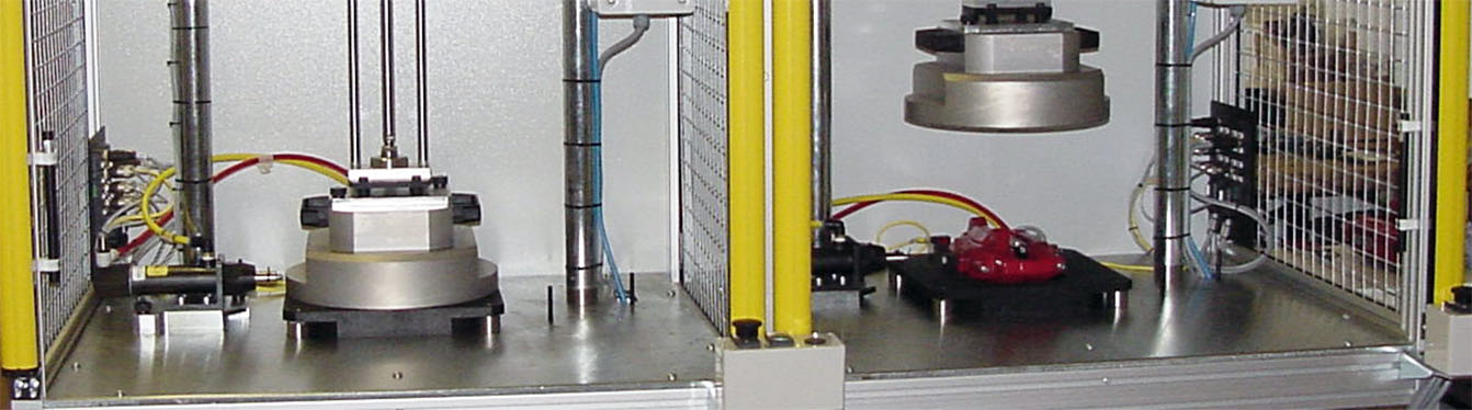
TQC designed and built a twin-station test bench that performs flow testing and three sequential leak tests using differential pressure decay methodology. While one station performs leak testing, the other performs flow testing, maximizing throughput. The system uses automatic shrouding chambers that seal around the brake assembly, creating test volumes for differential leak detection without requiring complex part-specific sealing interfaces.
Technical Overview – Brake Leak Testing
Twin-Station Architecture
The system uses two independent test stations mounted on a standard aluminium extrusion bench:
Station 1: Configured for flow testing and can alternate to leak testing
Station 2: Configured for leak testing and can alternate to flow testing
This parallel operation allows continuous testing – while one brake assembly undergoes the time-consuming three-stage leak test sequence, the operator can load, flow test, and unload another assembly at the second station.
Operator Workflow:
- Load brake assembly at Station 1, connect test line, initiate flow test
- While Station 1 flow tests, move to Station 2 and initiate leak test sequence
- Return to Station 1, unload tested part, load next part
- Alternate between stations for continuous operation
This approach effectively doubles throughput compared to a single-station system.
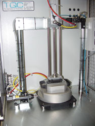
Automatic Shrouding Chamber
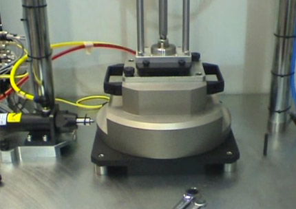
Each station includes an automatic sealing fixture that creates a test volume around the brake assembly:
Chamber Design: A close-fitting enclosure moves around the brake assembly and seals against a base plate. This creates a sealed chamber volume surrounding the external surfaces of the brake.
Differential Leak Testing Principle: The brake’s internal passages are pressurized with air. Any leak allows air to escape into the surrounding shroud chamber. The differential leak test instrument compares the pressure in the brake (supply side) against the pressure in the shroud chamber (test side) – any pressure increase in the chamber indicates leakage.
Advantages of Differential Testing:
- Extremely sensitive to small leaks
- Temperature-compensated (both volumes experience same temperature changes)
- Faster test times than absolute pressure decay
- No need for complex seals on irregular brake surfaces
Test Sequence – Brake Leak Testing
Flow Test (First Test)
Purpose: Verify that hydraulic passages within the brake are clear and that fluid can flow properly during operation.
Method:
- Air is supplied to the brake inlet at controlled flow rate
- Flow meter measures actual flow through the brake passages
- Flow reading is compared to acceptable range
- Blockage, debris, or manufacturing defects reduce flow below acceptable limits
Why This Comes First: Flow testing identifies gross defects (blockage, missing passages) quickly before performing the time-consuming leak tests. A blocked brake would fail leak testing anyway, so flow testing first saves time.
Result: If flow test fails, the part is rejected immediately without proceeding to leak testing.
Leak Test Sequence (Three Stages)
All three leak tests check for zero brake fluid leakage at different service pressure conditions. The tests are performed sequentially in ascending pressure order:
1. Intermediate Pressure Leak Test – 2 bar (29 psi)
Purpose: Verify seal integrity at normal braking pressures and check piston movement.
Method:
- Brake internal passages pressurized to 2 bar
- Pressure held for stabilization period
- Differential leak instrument monitors for pressure rise in shroud chamber
- Piston position sensors verify that pistons move as expected under pressure
Why 2 bar: Represents typical braking pressures during everyday driving conditions.
Piston Movement Check: Brake pistons must move freely under pressure. Stuck pistons indicate assembly issues and are detected at this stage.
2. Low-Pressure Leak Test – 0.5 bar (7 psi)
Purpose: Detect leaks that may only appear at very low pressures, such as check valve leaks or seal issues that close up under higher pressure.
Method:
- Brake pressurized to 0.5 bar
- Pressure held for stabilization
- Differential instrument detects any pressure rise in shroud
Why 0.5 bar: Some seal types may leak at low pressure but seal effectively at higher pressures. Testing at 0.5 bar catches these failure modes.
Why After 2 bar Test: Performing the 2 bar test first eliminates gross failures. Low-pressure testing is very sensitive and time-consuming, so running it on parts that already passed 2 bar testing improves efficiency.
3. High-Pressure Leak Test – Up to 160 bar (2,320 psi)
Purpose: Verify structural integrity and seal performance under extreme braking conditions (panic stops, high-performance driving).
Method:
- Brake pressurized to specified high pressure (35-160 bar depending on brake specification)
- Pressure held for stabilization
- Differential instrument monitors for any leakage
- High-pressure capable seals and connections used throughout test circuit
Why Up to 160 bar: High-performance brake systems can generate pressures above 100 bar during emergency braking. Testing at 160 bar provides safety margin and verifies the brake won’t fail under extreme conditions.
Safety: High-pressure testing is contained within the automatic chamber. Light guards prevent operator access during pressurization.
Control System of Brake Leak Test System
PLC-Based Control: A programmable logic controller manages all test sequencing, valve control, pressure regulation, and data acquisition.
Built-In Differential Leak Test Instrument: The system includes integrated differential pressure transducers that compare brake internal pressure against shroud chamber pressure. This provides highly sensitive leak detection with temperature compensation.
Operator Interface Panel: A standard operator interface panel provides:
- Test initiation buttons
- Real-time pressure displays
- Pass/fail indication lights
- Part counter
- Fault diagnostics
Safety Interlocks: Light guards at each station prevent operator access during high-pressure testing. Chamber closure is verified before pressurization begins.
Part Marking
Passed brake assemblies are automatically stamped or marked to indicate they have passed all tests. This provides:
- Visual confirmation of test status
- Traceability for quality documentation
- Prevention of untested parts entering assembly
Multi-Variant Tooling
Interchangeable tooling kits accommodate different brake sizes and configurations:
- Different shroud chamber sizes for various brake diameters
- Adjustable connection fittings for different port locations
- Quick-change mounting fixtures
- Minimal changeover time between variants
System Specifications
- Test Stations: 2 (parallel operation for maximum throughput)
- Throughput: Approximately 60 parts per hour (1 per minute)
- Flow Test: Air flow measurement with go/no-go criteria
- Leak Test Method: Differential pressure decay
- Test Pressures:
- Flow test: Controlled flow rate
- Leak test stage 1: 2 bar (29 psi)
- Leak test stage 2: 0.5 bar (7 psi)
- Leak test stage 3: 35-160 bar (507-2,320 psi) – adjustable per brake specification
- Chamber: Automatic sealing shroud around brake assembly
- Leak Detection: Built-in differential pressure transducers
- Control: PLC-based with operator interface panel
- Safety: Light guard access control at each station
- Part Marking: Automatic pass stamping
- Tooling: Interchangeable for multiple brake variants
- Bench Construction: Standard aluminium extrusion with universal fixture areas
- Based on: Series 40 standard leak testing platform
Key Features
Twin-Station Operation: Parallel testing maximizes throughput while one part undergoes time-consuming leak tests.
Sequential Test Logic: Flow test first eliminates blockage, then three-stage leak testing covers full pressure range.
Differential Leak Detection: Highly sensitive, temperature-compensated leak detection without complex part-specific seals.
Automatic Shrouding: Chamber automatically seals around brake assembly, eliminating manual sealing operations.
Wide Pressure Range: Tests from 0.5 to 160 bar cover all brake operating conditions.
Piston Movement Verification: Checks that brake pistons move correctly under pressure.
Multi-Variant Capable: Interchangeable tooling supports different brake sizes without system modification.
High-Pressure Safety: Automatic chambers and light guards protect operators during 160 bar testing.
Results
The twin-station leak and flow test system provides complete production acceptance testing for high-performance disc brake assemblies at approximately 60 parts per hour. Sequential flow testing followed by three-stage leak testing ensures brake assemblies meet hydraulic integrity requirements across the full operating pressure range from light braking (0.5 bar) through normal operation (2 bar) to extreme braking conditions (160 bar).
Differential leak testing with automatic shrouding chambers provides sensitive leak detection without requiring complex sealing interfaces specific to each brake variant. The twin-station architecture maintains throughput by allowing parallel operation of flow and leak testing.
Automatic pass marking provides traceability and prevents untested parts from entering assembly operations.
Related Capabilities
This project demonstrates TQC‘s expertise in:
- Automotive brake system testing
- Differential pressure decay leak testing
- High-pressure leak testing (up to 160 bar)
- Flow testing for hydraulic components
- Multi-stage sequential testing
- Twin-station test systems for high throughput
- Automatic shrouding chamber design
- PLC-based test control
- Series 40 standard leak test platform
- Interchangeable tooling for variant flexibility
- Automotive production environments
To view a printer friendly format please click below
Automotive Brake Leak and Flow Testing
If you need leak and flow testing for brake systems, hydraulic components, or other automotive applications, contact TQC to discuss your requirements.