Leak Test Fixture with Interchangeable Tooling
Client: Leading Aluminium Die Casting Company
Part: Various Automotive Die Cast Parts (4 Variants)
Machine supplied: Series 10 Leak Test Fixture with Interchangeable Tooling
Test Method: Air Decay Pressure Testing with MALT Controller
Configuration: Bench-Mounted with Toggle Clamp
Changeover: SMED Principles (Single Minute Exchange of Die)
Cycle Time: <1 Minute Per Part
Capability: 100% Testing of Low-Volume Multi-Variant Production
The Challenge
A leading aluminium die casting company producing automotive components needed cost-effective 100% leak testing for low-volume, multi-variant production. The requirements included:
- Testing four different die cast part variants on single fixture
- Rapid changeover between variants (minutes, not hours)
- Test sensitivity detecting small casting porosity
- Accommodation of large-area parts (complex geometry)
- Operator-friendly loading and unloading
- Storage for unused tooling sets
- Pass/fail marking integrated with testing
- Cost-effective solution for low production volumes
Dedicated leak test machines for each variant were economically unjustifiable for low volumes. The company needed flexible testing accommodating variant changes throughout the day, via interchangeable tooling, while maintaining sensitivity and throughput.
Die cast aluminium parts in automotive applications create critical leak paths:
- Engine components (oil galleries, coolant passages)
- Transmission housings (hydraulic fluid circuits)
- Brake components (hydraulic pressure retention)
- Steering assemblies (power steering fluid containment)
Casting porosity (inherent in die casting process) creates leak paths that compromise:
- Fluid pressure retention (performance degradation)
- Cross-contamination between circuits (system failures)
- External leakage (environmental concerns, customer complaints)
- Component structural integrity (progressive failure)
Manual testing lacked repeatability, and dedicated fixtures per variant consumed excessive capital and floor space.
The Solution
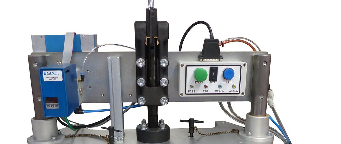
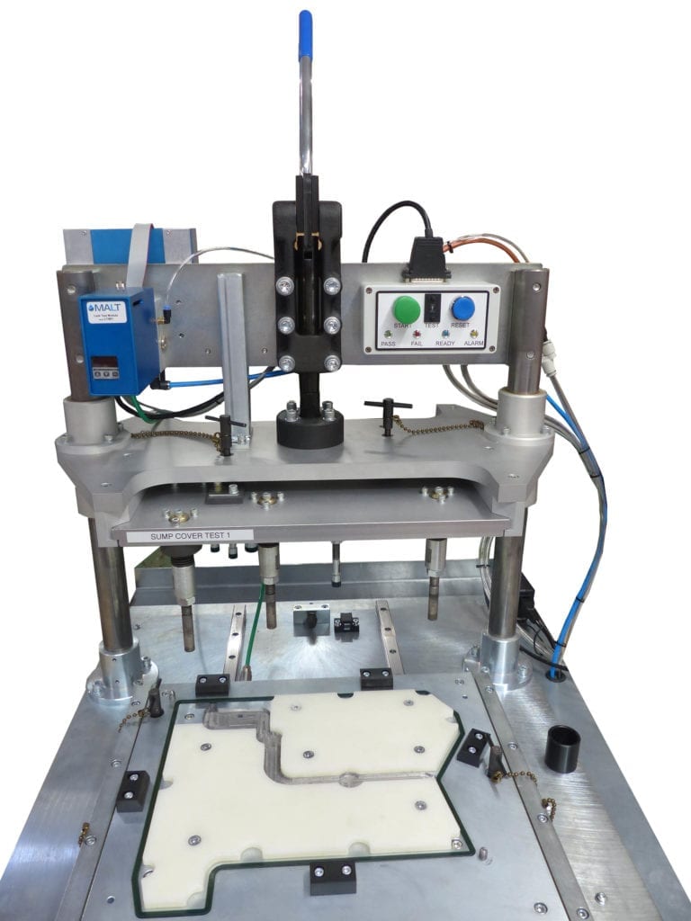
TQC designed a Series 10 bench-mounted leak test fixture with four interchangeable tooling sets. The fixture uses a manual toggle clamp securing parts against custom polyurethane seals in the bottom tooling. A slideway mechanism enables operator loading at forward position, then sliding the part back to a second position under the toggle clamp for testing. Bespoke infill pieces reduce test volume (increasing sensitivity), while spring-loaded pins apply controlled clamping pressure. Top and bottom tooling plates exchange in minutes using SMED principles. An OEM MALT LT401 controller provides air decay leak testing with pass/fail results. Integrated pass stamping marks verified parts. The bench includes storage cabinets for unused tooling sets and spare seals. Test cycle time under 1 minute enables 100% verification at production rates.
Technical Overview – Interchangeable Tooling Leak Test Solution
Series 10 Bench-Mounted Fixture Platform
Standardised Leak Test Architecture: The Series 10 fixture provides the mechanical framework for interchangeable tooling:
Series 10 Design Features:
- Heavy-duty bench-mounted base (stable platform for toggle clamp forces)
- Precision-machined mounting interface for tooling plates
- Integrated pneumatic connections to MALT controller
- Operator button box with start/stop controls
- Visual indicators (pass/fail lights, test-in-progress)
Bench Configuration:
- Work surface at ergonomic height (750-900mm)
- Storage cabinets below bench (houses unused tooling sets)
- Shelving for seal storage and consumables
- Operator access from front (part loading/unloading)
- Space-efficient footprint (single fixture vs. four dedicated machines)
Why Series 10 Platform: TQC‘s standardised fixture system provides:
- Proven reliability in production environments
- Modular design accepting custom tooling
- Rapid deployment (standard platform, custom tooling only)
- Lower cost than fully custom fixtures
Interchangeable Tooling – Top and Bottom Tooling
Four Tooling Sets for Four Variants: Each variant requires dedicated tooling capturing part-specific geometry:
Bottom Tooling Plate:
- Precision-machined aluminium or steel plate
- Part nest (locates component in X, Y, Z axes)
- Seal groove (houses custom polyurethane seal)
- Pneumatic porting (connects to MALT for pressurisation)
- Location blocks (quick part alignment)
Top Tooling Plate:
- Matching geometry to bottom plate
- Spring-loaded pins (apply pressure at bolt locations)
- Pneumatic actuation ports (if required for seal activation)
- Clearance for toggle clamp mechanism
Tooling Plate Interface:
- Precision dowel pins (repeatable positioning on Series 10 base)
- Clamp slots or T-nuts (secure tooling to base)
- Quick-release fasteners (enable rapid exchange)
Tooling Storage:
- Unused sets stored in bench cabinets
- Protected from damage (dedicated compartments)
- Labelled for variant identification
- Spare seal sets organised by variant
SMED Changeover Methodology
Single Minute Exchange of Die Principles: Tooling changes execute in minutes:
SMED Implementation:
Internal Operations (Fixture Must Be Idle):
- Unclamp Current Tooling: Release quick-release fasteners (typ. 4-8 fasteners)
- Lift Top Plate: Remove upper tooling, place in storage
- Slide Bottom Plate: Extract bottom tooling from base
- Install New Bottom Plate: Slide replacement onto base, align dowel pins
- Secure Bottom Plate: Tighten quick-release fasteners
- Install New Top Plate: Position upper tooling, secure
- Connect Pneumatics: Verify air connections to MALT (quick-disconnect fittings)
External Operations (Prepared Before Stoppage):
- New tooling set retrieved from storage
- Operator identifies correct variant set
- Seal condition verified (no damage or wear)
- MALT controller parameters loaded (variant-specific test recipe)
Why SMED Matters: Low-volume production requires frequent changeovers. SMED principles:
- Minimise downtime (minutes vs. hours for dedicated machines)
- Enable mixed-variant production (respond to daily demand)
- Maintain operator productivity (simple, repeatable process)
Slideway Mechanism for Large Parts
Two-Position Loading System: Large die cast parts require special handling:
Slideway Operation:
Position 1 (Front – Load / Unload Position):
- Bottom tooling plate extended forward
- Clear access for part placement
- Operator lowers part into nest
- Location blocks guide alignment (visual confirmation)
Position 2 (Rear – Test Position):
- Operator slides bottom plate rearward (manual push or pneumatic assist)
- Part and bottom tooling translate together (part remains nested)
- Final position places part under toggle clamp mechanism
- Slideway locks in test position (prevents movement during clamping)
Why Slideway Design:
- Large parts (complex geometry, extended dimensions) difficult to insert vertically under toggle clamp
- Forward loading provides clear access without interference
- Horizontal sliding simple, reliable motion
- Ergonomic: Reduces operator bending and awkward positioning
Slideway Construction:
- Linear bearing rails (smooth, low-friction travel)
- Hardened steel sliders (long service life)
- Positive stops at both positions (repeatable placement)
- Interlock sensors (prevent test if not in rear position)
Manual Toggle Clamp System
Operator-Actuated Clamping: Toggle clamp provides mechanical advantage:
Toggle Clamp Operation:
1. Open Position:
- Operator releases toggle clamp lever
- Top tooling plate rises
- Clear access for part loading/unloading
2. Part Loading:
- Operator places part in bottom tooling nest (via slideway at front position)
- Slides bottom tooling to rear test position
3. Clamping:
- Operator pulls toggle clamp lever over-centre
- Mechanical linkage forces top tooling downward
- Part compresses against bottom tooling seal
- Spring-loaded pins clamp part
- Clamp locks in closed position (over-centre mechanism)
4. Test Execution:
- Operator presses start button
- MALT executes air decay test
- Pass/fail indication displays
5. Unload:
- Operator releases toggle clamp
- Part slides forward for removal
Toggle Clamp Advantages:
- High clamping force from low operator effort
- Repeatable clamping pressure (mechanical over-centre design)
- No pneumatic/hydraulic systems required (simple, reliable)
- Immediate release (no wait for cylinder retraction)
Clamping Force Distribution:
- Toggle clamp centre-mounted on top tooling
- Force distributed via top plate to spring-loaded pins
- Pins apply localised clamping pressure at bolt locations (simulate installed condition)
- Uniform seal compression around part perimeter
Custom Polyurethane Seals
Part-Specific Sealing Surfaces: Each variant tooling includes bespoke seals:
Seal Design Process:
- Part Geometry Analysis: 3D CAD model identifies sealing surface
- Seal Profile Design: Cross-section optimised for compression and sealing
- Material Selection: Polyurethane durometer (hardness) selected for part geometry and test pressure
- Seal Fabrication: Moulded using custom tooling to precise dimensions
Seal Installation:
- Groove machined in bottom tooling plate
- Seal pressed into groove (mechanical retention)
- Seal protrudes above plate surface (typically 2-5mm)
- Compression when clamped creates leak-tight seal
Why Polyurethane:
- Excellent compression set resistance (maintains sealing over thousands of cycles)
- Chemical resistance to test media (air, nitrogen)
- Abrasion resistance (tolerates part surface variations)
- Wide hardness range (30-90 Shore A) accommodates different applications
Seal Maintenance:
- Visual inspection before each shift (damage, wear, contamination)
- Spare seals stored in bench shelving
- Seal replacement: Minutes (remove worn seal, install replacement)
Bespoke Infill Tooling for Volume Reduction
Test Sensitivity Enhancement: White plastic infills reduce test volume:
Why Volume Reduction Matters:
- Air decay sensitivity inversely proportional to test volume
- Large die cast parts create large internal volumes
- Large volumes require longer fill/stabilisation times or reduce sensitivity
Volume Reduction Example:
- Original part volume: 5000 mm³
- With infills: 1500 mm³
- Sensitivity improvement: 3.3× (same leak rate produces 3.3× greater pressure change)
Infill Design:
- Custom-shaped plastic blocks filling non-critical internal spaces
- Material: Low-density polymer (white colour for easy identification)
- Integrated into tooling
- Displace air reducing test volume to critical leak path areas only
Infill Benefits:
- Faster test cycles (smaller volume stabilises quicker)
- Higher sensitivity (detects smaller leaks)
- Lower test pressure possible (less stress on seals and fixtures)
Spring-Loaded Pins at Bolt Locations
Simulating Installed Condition: Pins apply clamping force at fastener locations:
Pin Configuration:
- Mounted in top tooling plate
- Positions correspond to part bolt holes or mounting points
- Spring-loaded (compression springs behind each pin)
- Pin tips contact part surface (or insert into bolt holes)
Why Spring Loading:
- Part-to-part dimensional variation (casting tolerances, machining)
- Fixed pins would either not contact (loose parts) or over-compress seals (tight parts)
- Springs provide compliant loading (each pin adapts to local part height)
- Spring washers ensure consistent pressure across all pins
Clamping Function:
- Toggle clamp compresses entire top tooling downward
- Spring-loaded pins compress, applying force at bolt locations
- Simulates installed condition where fasteners compress part against mating surface
- Prevents part distortion during test (unclamped areas might deform under pressure)
Spring Selection:
- Spring rate chosen for consistent force (typ. 10-50N per pin)
- Sufficient travel (5-10mm) accommodates part variation
- Spring washers in series provide additional compliance
OEM MALT LT401 Controller
Multi-Application Leak Tester Integration: MALT provides test instrumentation:
MALT LT401 Specifications:
- Compact valve module (mounts near fixture)
- Integrated pressure sensor (high accuracy and resolution)
- Pass/fail outputs (visual/audible indicators, part marking trigger)
Air Decay Test Sequence:
1. Fill Phase:
- MALT valve opens, pressurising part
- Pressure monitored until target reached
- Gross leak check: If pressure doesn’t reach target, fail immediately
2. Stabilisation Phase:
- Valve closes, isolating part
- Stabilisation time (pressure equalises, temperature stabilises)
- Turbulence from filling settles
3. Test Phase:
- Pressure measured at start and end of test period
- Pressure decay calculated: ΔP = P_start – P_end
- Comparison to threshold
4. Pass/Fail Decision:
- Decay < threshold: Pass (acceptable leak rate)
- Decay > threshold: Fail (excessive leak)
5. Vent Phase:
- Exhaust valve opens, depressurising part safely
- Ready for next test
Button Box Interface:
- Start button (operator initiates test)
- Stop/Reset button
- Pass/fail indicator lights (green/red)
- Test-in-progress indicator (yellow)
Test Recipe Storage:
- Multiple recipes stored in MALT controller
- Each recipe contains variant-specific parameters (pressure, time, threshold)
- Recipe selection via front panel or automatic (if barcode scan implemented)
Integrated Pass Stamping
Automatic Part Marking: Pass stamp marks verified parts:
Stamp Configuration:
- Pneumatic stamp mechanism (MALT pass output triggers)
- Percussion marker
- Positioned to mark accessible part surface
- Mark visible for downstream verification
Stamping Operation:
- Test completes, MALT determines pass/fail
- If pass: MALT energises stamp solenoid
- Pneumatic cylinder extends stamp, marks part
- Stamp retracts
- Operator removes marked part
Why Integrated Marking:
- Prevents mixing of tested/untested parts
- Visual confirmation for downstream operators
- Traceability (date/shift codes possible with programmable markers)
- Eliminates separate marking step
Storage and Organisation
Bench Storage System: Integrated storage maintains organisation:
Cabinet Storage:
- Unused tooling sets (3 sets stored while 1 in use)
- Protected compartments prevent damage
- Labelled for quick identification
Shelf Storage:
- Spare seal sets (organised by variant)
- Documentation (tooling change procedures, test parameters)
Organisation Benefits:
- Rapid changeover (tooling immediately accessible)
- Prevents damage (dedicated storage vs. floor storage)
- Inventory visibility (spare seals, consumables)
- Operator efficiency (no searching for components)
System Specifications – Interchangeable Tooling Leak Test Solution
- Platform: Series 10 bench-mounted leak test fixture
- Configuration: Manual toggle clamp with slideway loading
- Tooling Sets: 4 interchangeable top/bottom plate sets (4 variants)
- Changeover: SMED principles (3-8 minute tooling exchange)
- Controller: OEM MALT LT401 valve module and controller
- Test Method: Air decay pressure testing (1-5 bar typical)
- Seals: Custom polyurethane seals per variant
- Infills: Bespoke plastic volume-reduction inserts
- Clamping: Spring-loaded pins at bolt locations
- Marking: Integrated pass stamp (pneumatic actuation)
- Cycle Time: <1 minute per part
- Storage: Bench cabinets and shelving for tooling/seals
- Application: Automotive aluminium die cast components
Key Features
Interchangeable Tooling: Four variant sets enable multi-part production on single fixture, eliminating dedicated machine costs.
SMED Changeover: Quick-release fasteners and dowel pin alignment enable tooling exchange in minutes.
Slideway Loading: Large parts load at front position, slide back for testing, improving ergonomics and access.
Manual Toggle Clamp: High clamping force with low operator effort, no pneumatic/hydraulic complexity.
Custom Polyurethane Seals: Bespoke seal profiles optimised per variant, good service life.
Bespoke Infills: Volume reduction increases test sensitivity 2-3×, enabling detection of smaller casting porosity.
Spring-Loaded Pins: Compliant clamping at bolt locations simulates installed condition, prevents part distortion.
MALT LT401 Controller: Proven air decay instrumentation with recipe storage for variant-specific parameters.
Integrated Pass Stamping: Automatic marking of verified parts prevents mixing with untested stock.
Organised Storage: Bench cabinets and shelving house unused tooling and consumables within arm’s reach.
Results – Interchangeable Tooling Leak Test Solution
The Series 10 leak test fixture with interchangeable tooling provides cost-effective 100% testing for low-volume, multi-variant die cast production. Four tooling sets on a single bench-mounted fixture eliminate the capital expense of four dedicated machines while maintaining test sensitivity and throughput.
SMED-based changeover executes in minutes, enabling mixed-variant production responding to daily demand. Quick-release fasteners and dowel pin alignment make tooling exchange simple and repeatable without special skills.
The slideway mechanism accommodates large, complex die cast parts with ergonomic loading at the forward position. Manual toggle clamp provides repeatable high clamping force without pneumatic/hydraulic systems, reducing complexity and maintenance.
Custom polyurethane seals optimised per variant achieve gas-tight sealing across thousands of test cycles. Bespoke infills reduce test volume by 60-70%, increasing sensitivity 2-3× and enabling detection of small casting porosity that larger test volumes would miss.
Spring-loaded pins apply compliant pressure at bolt locations, simulating the installed condition and preventing part distortion during pressurisation. The MALT LT401 controller provides proven air decay testing with recipe storage accommodating variant-specific test parameters.
Integrated pass stamping marks verified parts, preventing mixing with untested stock. Organised bench storage houses unused tooling and consumables, enabling rapid changeover and maintaining production flow.
Test cycle time under 1 minute achieves 100% verification at production rates, eliminating the risk of shipping parts with casting porosity that would cause field failures.
To view a printer friendly format please click below
Leak Test Fixture with Interchangeable Fixtures
If you have an application that could benefit from TQC’s expertise in leak testing and interchangeable tooling design, please contact us by email or phone via the contact details